Image
Archive
People

Archive related to construction and test flights of the Concorde 002 prototype aircraft

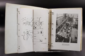
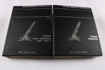
Collection of documents relating to Skylark sounding rocket, predominantly to the development of Attitude Control Units
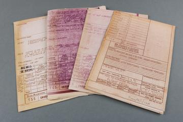
Skylark Users Handbook, Volumes 1 and 2

Skylark Stage 5 Phase 2 Attitude Control Unit Dynamic Test Schedule

2 boxes

Technical and publicity material related to UK3 (Ariel 3) satellite project

1 box

Collection Relating to Exhibitions Celebrating Alcock & Brown

1 item

Concorde overall dimensions drawing. Fig. 1-9

1 drawing

Drawing entitled 'Functional Diagram for Fuel System'

1 drawing

Drawing entitled 'View Looking Fwd. on Starb. Jack''

1 drawing

Drawing entitled 'Alterations to Intake Ramp Mechanism. Bay 2.'

1 drawing

Drawing entitled 'Main Hinge & Sliding Mech. Assy. (Passenger Door)'

1 drawing

Drawing entitled 'Ensemble Schema Circuit Hydraulique Avion 01.'

1 drawing

Drawing entitled 'Ensemble Meuble Ingenieur Avion 002 Seulement.'

1 item

Flight deck drawing routing chart. Fig. 10-3.

1 drawing

Drawing entitled 'Ensemble Extrados Voilure Gauche (Pre_Serie)'

1 drawing

Drawing entitled 'Centre Boom Frame 93.32 (Intake 4)'

1 drawing

Drawing entitled 'Ensemble Schema Circuit Hydraulique Avion 01.'

1 drawing

Drawing entitled 'Systeme de Climatisation'

1 drawing

Drawing entitled 'Functional Diagram for Fuel System'

1 drawing

Drawing entitled 'G.A of Flight Deck (Prototype) Fig. 10-2.'

1 item

Nose, port and starboard undercarriage, Flight 74

1 drawing

Drawing entitled 'Troncon 20, Montage Clapet de Securite Degazeur Baches.'

1 item

Circuit diagram No. 31. Lateral thrust units. Sheet 1.

1 item

Section 10. Flight Deck Data and Group Assemblies. Drawing Nos. D-91-6100, D-91-6101 & D-91-6140

1 item

Plan de forme karman, part A. Fig. 3-6.

1 drawing

Drawing entitled 'G.A. of Camouflage & Identn. (Air Transfers)'

1 item

Circuit diagram No. 9. Fuel transfer & fuel pressure failure. Sheets 1 & 2.

1 drawing

Drawing entitled 'Application of Viton to 'A' Panel Heat Shields. All Bays.'

1 drawing

Drawing entitled 'Intake Geometry'

1 drawing

Drawing entitled 'Layshaft Assembly (Top)'

1 drawing

Drawing entitled 'Drawing Routing Chart Nose Fairing & Visor. Fig. 9-11.'

1 item

Bristol T.221 Circuit Diagrams Book, contents sheet.

1 drawing

Drawing entitled 'Diagram of Airflows. Production Aircraft.'

1 drawing

Drawing entitled 'Bielle Reglable'

1 drawing

Drawing entitled 'Diaphragm'

1 drawing

Drawing entitled 'Drawing Routing Chart Intermediate Fuselage. (Major Static Test Specimen). Fig. 9-9.'

1 drawing

Drawing entitled 'Functional Diagram for Fuel System'

1 drawing

Drawing entitled 'Fuselage to Wing Attachments Geometry. Fig. 2-8.'

1 item

TSS 002. Compte-redu de reunion tenue a Fairford.

1 drawing

Drawing entitled 'Fuel System'

1 item

Circuit diagram No. 40. Instrumentation control.

1 drawing

Drawing entitled 'Functional Diagram for Fuel System'

1 drawing

Drawing entitled 'Ensemble Schema Circuit Hydrayulique Avion.'

1 drawing

Drawing entitled 'Semi-Equipements Codifies du Circuit de Condt. D'Air'

1 drawing

Drawing entitled 'Key Diagram - Rear Fuselage. Fig. 2-20.'

1 drawing

Drawing entitled 'Altn. To Ramp Link Attachment Housing.'

1 drawing

Drawing entitled 'Fuel System Diagram -Production'

1 item

Assembly of systems layouts. BAC zone. Fig. 8-3.

1 drawing

Drawing entitled 'Systeme de Climatisation'

1 item

Structure trappe